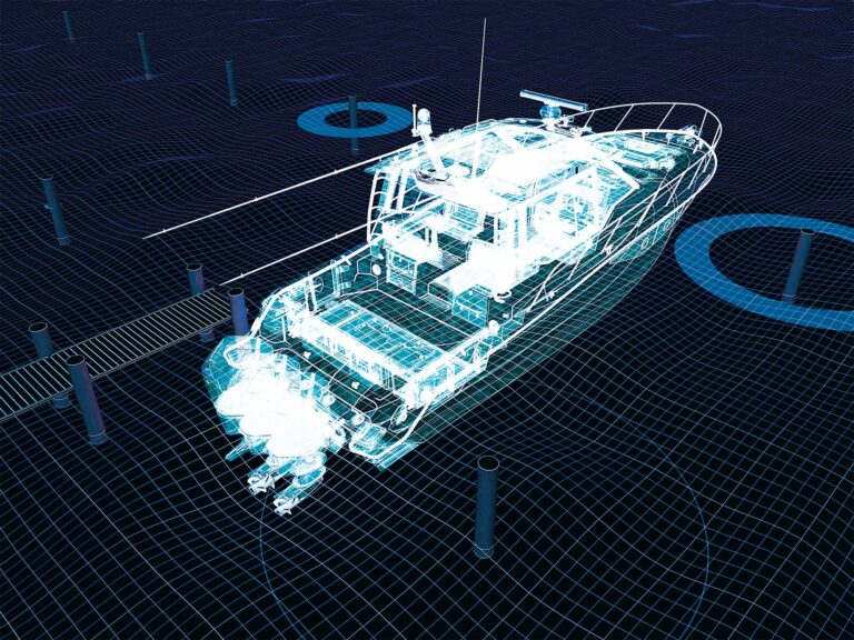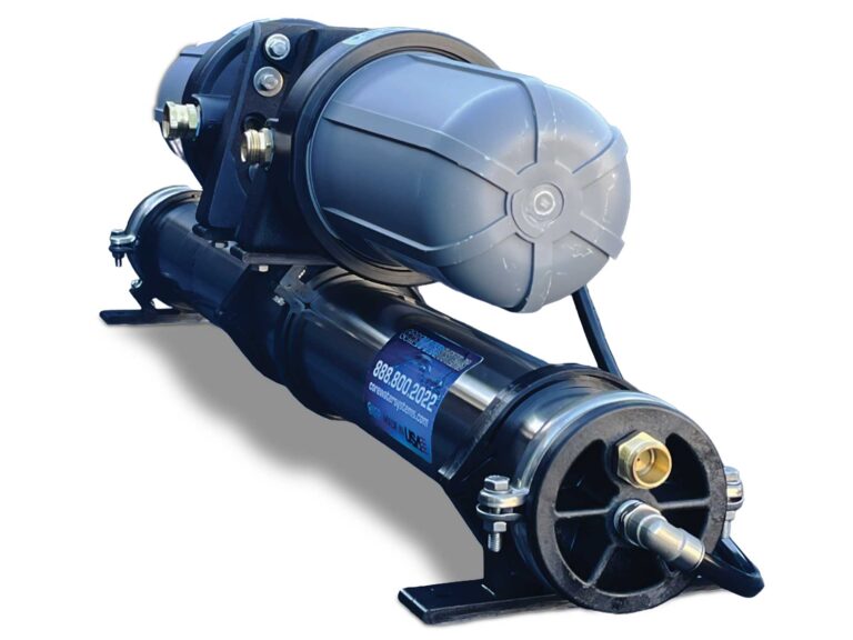
Dometic’s new Xtreme Power Assist offers innovative benefits to boaters on a number of levels. For one, it’s the only power-assist system for outboard-powered boats with cable steering. Secondly, it’s easy to install for DIYers. Thirdly, it makes steering an outboard—be it at idle or at speed—super-easy, greatly reducing the effort to turn the wheel.
Using a compact and advanced brushless electric-motor system, XPA is engineered for use with Dometic’s popular SeaStar rack or rotary cable steering systems to provide fingertip control at the wheel. Yet, XPA does not increase the load on the mechanical helm or the steering cable.
XPA fills a niche in the boating market for midrange outboards 90 to 200 hp, providing a more affordable and simpler alternative to other types of power-assist such as Dometic’s SeaStar hydraulic power-assist or Optimus all-electric steering.
XPA attaches to the outboard steering bracket and draws its power from the boat’s onboard 12-volt DC electrical system. Before getting started, make sure that there is proper clearance at the transom, as specified in the installation instructions. This is to ensure that the outboard has room to turn unimpeded from side to side, as well as tilt and trim up and down. Also, disconnect or turn off the battery switch before getting started.
This installation took place on an 18-foot center-console boat powered by a 115 hp outboard with a SeaStar Safe-T Quick-Connect rotary steering system.
Skill Level: 2 of 5
Finish Time: Approx. 2 hours
Tools and Supplies
- Dometic Xtreme Power Assist with a 12-foot wire harness ($1,499; amazon.com)
- Socket and open/box wrench sets
- Torque wrench (3/8-inch drive model with digital scale; amazon.com)
- Power drill and bit set
- Electricians snake (to route wire harness)
- Marine-grade crimps with heat-shrink collars
- Wire striper and crimping tool
- Heat gun
- Zip-ties (to secure wire harness along its run)
- Marine grease
- Shop rags (to wipe away excess grease)

Spacer and Adapter
Tilt the engine down, and remove the link arm from the steering cable ram. Remove the nut for the steering cable, and pull it from the tilt tube. Because you are installing a new steering system, we strongly advise that you install a new cable as well. Clean and lube the cable ram and tilt tube with marine grease. Determine if the supplied cable adapter or split plastic cable spacer will be required for your outboard based on the chart provided in the installation-requirements section of the instructions. If so, add the cable adapter or split plastic cable as instructed. Reinstall the cable and nut, then torque the nut to 25 lb.-ft.

Mounting Bracket
Ensure that the mounting holes on the front of the tilt tube housing are free of dirt and debris. Based on the chart in the installation-requirements section of the instructions, determine if body spacer shims are required for the mounting bracket and which ones to use. Attach the mounting bracket to the engine tilt tube housing. Verify that the mounting bracket doesn’t prevent access to the grease fittings. If it does, remove and plug the grease fittings, or replace them with fittings that are flush to the engine. Tighten the fasteners in a cross pattern, ensuring that they are fully seated against the mounting bracket. Torque to 75 lb.-in.

Retraction Spacers and Clevis Sleeve
Determine if your engine requires retraction spacers by checking for the model in the chart provided in the installation-requirements section of the instructions. Slide the required number of retraction spacers onto the steering cable ram. Then slide the clevis nut over the steering cable ram. Next, determine the proper clevis sleeve from among the two supplied in the installation kit (there’s one green and one black) for your outboard engine model in the chart provided in the installation-requirements section of the instructions. Slide the correct clevis sleeve onto the steering cable ram.

Mount XPA
Slide the XPA onto the studs of the mounting bracket, followed by the supplied washers. Secure the XPA with the supplied anti-seize 1/2-inch nuts. Torque to 150 lb.-in. Align the holes of the steering ram and the clevis sleeve. Insert the clevis pin through the sleeve and steering ram holes. Twist the steering ram, aligning the flats with the pin in a horizontal orientation. Hold the clevis pin in place, and guide the clevis sleeve and steering cable ram into the sensor housing while a buddy turns the steering wheel. Slide the clevis nut into the sensor housing and thread it on by hand. The sleeve must be fully seated. Torque to 150 lb.-in.
Read Next: Dometic SeaStar XPA Steering

Install Link Arm
Apply marine grease to the shoulder area above the threads on the engine link arm, then insert the link arm (which is connected at the other end to the outboard tiller arm) into the XPA sensor housing, but don’t secure the 3/8-inch thin locknut at this time. Inspect the complete assembly to check that it is properly seated and free from any restriction or binding. Ensure that all XPA power cables are secure and free of sharp bends and potential chafing. Secure the supplied 3/8-inch thin locknut, making sure the locking feature of this nut is engaged with the threads on the link arm. Fully tighten the nut, then unscrew between 1/4 and 1/2 of a turn.
Connect to Power
Turn off all power to the boat. Identify a location for the status-light installation on the boat’s dash that’s readily visible when at the helm. Drill a 11/64-inch-diameter hole into the dash at the chosen location. Install the LED status light into the hole. Next, route the XPA wire harness to the boat’s battery without making hard turns or pressing the harness against sharp surfaces. Install the supplied 40-amp fuse holder according to the instructions included in the kit. Route the purple and gray wires to the dash. Splice the purple ignition sensing wire of the XPA to the boat’s key-on power lead. This wire must deliver 12 volts DC when the ignition is on. Next, splice the gray wire to the yellow wire of the LED status light and the light’s red wire to a 12-volt DC power source. Next, connect the black wire from the XPA harness to the negative terminal of the boat battery. Then connect the red overcurrent-protected harness to the positive terminal of the battery. Restore power to the boat, and make sure the system is operating properly.

